Copper Cabling Certification: What to Require Before Project Closeout
A practical acceptance checklist for commercial copper cabling: choose the right test model, review certification results, reconcile labels, and collect a usable closeout package.
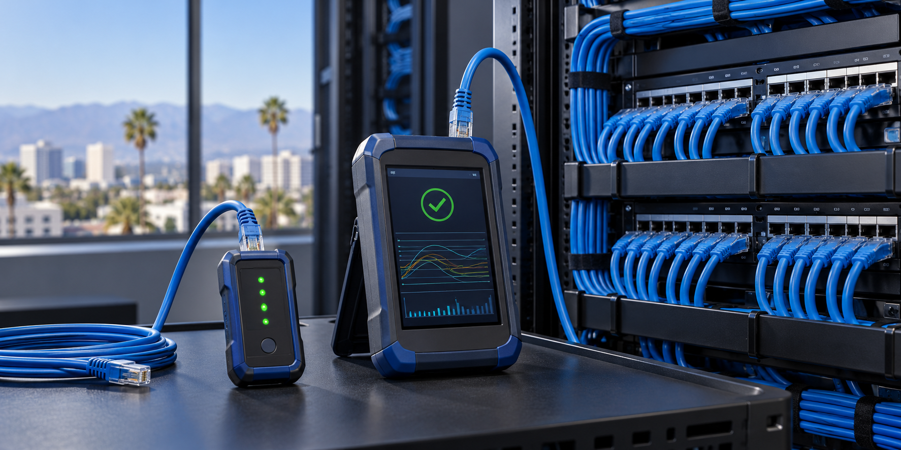
A new office can appear ready for occupancy while the copper cabling behind its access points, cameras, desks, and conference rooms has never been proven against the performance promised in the scope. A continuity light is useful, but it is not evidence that a Category 6 or 6A link meets the specified performance limit. Treating those two tests as interchangeable can defer a costly fault until after ceilings close and staff move in.
First, define what “tested” means
Verification, qualification, and certification answer different questions. A verification tester checks basic connection and wiring faults; a qualification tester assesses whether a link supports a particular application; a certification tester measures the installed link against a selected cabling standard and reports pass or fail. Fluke Networks explains the distinction between these test classes. For a new installation specified as a particular category, write the required certification test and deliverables into the purchase order rather than accepting the undefined phrase “all cables tested.”
Specify the link model before anyone presses Test
The test setup must match what was installed and what the owner is accepting. A permanent-link test evaluates the fixed cabling between the patch panel and outlet; a channel test includes the connecting cords used in that channel. For a device served by a field-terminated plug rather than a conventional outlet, specify the appropriate modular plug terminated link (MPTL) test configuration instead of assuming a standard permanent-link adapter tests the plug correctly. Fluke Networks describes its MPTL adapter arrangement. Identify the category, test limit, link model, cable and connecting hardware, and any owner or manufacturer warranty requirements in the acceptance plan.
Build a test schedule from the design
- Assign one identifier per installed link: map outlet or device position to panel, port, room, and served system before testing begins.
- Include every installed run: spare and dark drops are part of the delivered asset, not optional future work.
- Record the intended topology: note conventional outlets, direct-connect camera or access-point plugs, consolidation points, and approved exceptions.
- Agree on failure handling: define who repairs, retests, approves deviations, and updates closeout drawings.
Inspect the physical installation before accepting a pass
A tester cannot document everything visible in the field. Walk a representative sample of pathways and all critical rooms: confirm supports and protection are appropriate for the route, service loops are manageable, labels are readable at both ends, and terminations and patch panels match the schedule. Check that cable is not visibly crushed, sharply bent, or pulled tight at the connector. Coordinate firestop and separation observations with the project documents and applicable requirements; a network test result is not a substitute for those inspections.
Review the actual measurements, not only a green icon
Depending on the selected standard and test limit, copper certification instruments report more than wire map and length: measurements can include insertion loss, return loss, near-end crosstalk, propagation delay, delay skew, and resistance-related parameters. Fluke Networks lists the supported measurement parameters and notes that the selected test standard determines what is reported. Review the configured limit and adapter type, link ID, overall result, and marginal or failed parameters. A pass against the wrong limit or link model does not prove the specified installation was accepted correctly.
- Check setup: confirm the selected category, limit, link model, instrument configuration, and test date.
- Check traceability: select links from the drawing and locate their corresponding native test records; then select test records and find their physical labels.
- Check exceptions: review failures and borderline results individually, document repairs, and keep the final retest record tied to the same link ID.
- Check after changes: retest links affected by a retermination, relocated outlet, or other physical change before closeout.
Close out with an auditable package
Require the final outlet and panel schedule, marked-up as-built drawings, native tester files plus a readable summary, the selected test limits, instrument identity and current calibration documentation, repair and retest log, and a list of unresolved exceptions approved by the owner. Match test counts to installed link counts, allowing for documented exclusions. Store the files where the facilities and IT teams can retrieve them when a port fails or a system is expanded.
A link is not truly turned over when its status cannot be traced from the wall label to the drawing and the final test record.
What this prevents—and what it does not
Certification establishes evidence about the installed cabling under its selected test conditions. It does not by itself validate VLAN assignment, switch configuration, PoE budget, camera operation, or the complete user experience. Commission those systems separately and retain their results alongside the cabling package. This division of responsibility makes a later fault easier to isolate without overstating what any one test proves.
How SkaiCloud Network can help
SkaiCloud Network can help Southern California owners define copper cabling scope, coordinate installation and labeling, specify appropriate acceptance tests, and assemble a field-usable closeout package alongside the network commissioning plan. Before authorizing final turnover, ask for the link schedule and a sample of native test files; if the identifiers or test limits cannot be reconciled, resolve the gap while the work is still accessible. Discuss a cabling acceptance and network commissioning plan with SkaiCloud Network.